Last Updated on May 27, 2026
Ethernet cables, or as many people call them networks cables are used for data transmission between devices on a network. They consist of a cable with 4 pairs of wires connected by RJ45 connectors on each end although it’s possible to have a different type of connection for special uses.
Most Ethernet cables in use today are either Category 5e or Category 6 (and even Cat7) which is often abbreviated as Cat5e or Cat6 etc. Cat5e and Cat6 offer higher data transfer rates than the older types such as Cat5 and Cat4. They are most often used for Gigabit connections. Ethernet cable signals are generally good for around 300 feet distance wise before the signal has to be regenerated with a device such as a switch or hub.
But don’t go thinking all Ethernet cables are the same. They can be wired as straight or crossover. We will break down exactly how these pinouts work and how to build them yourself.
The Core Differences Between Cable Types
1. Understand Straight Through Cables
Straight is the most common type of network wiring in existence today. You use this standard configuration to connect things like computers to hubs or network switches. You also use them to connect your home PC directly to your broadband router. They are most likely what you will find when you go to your local computer store and buy a patch cable off the shelf.
2. Understand Crossover Cables
Crossover cables serve a very specific hardware purpose. You use them to connect a computer directly to another computer without a router sitting in the middle. You also use wireless network alternative setups or crossover cables to link two or more switches together. They are much harder to find in retail stores since they are not used nearly as much as straight through cables.
3. Learn About Auto-MDIX Technology
Modern network switches use a software technology called Auto-MDIX. This protocol automatically detects the required cable connection type and configures the port pins appropriately. This means a modern gigabit switch can use a standard straight cable to connect to another switch without failing. You still absolutely need specialized crossover cables for older legacy hardware and direct server-to-server connections.
How to Visually Identify Your Cable Type
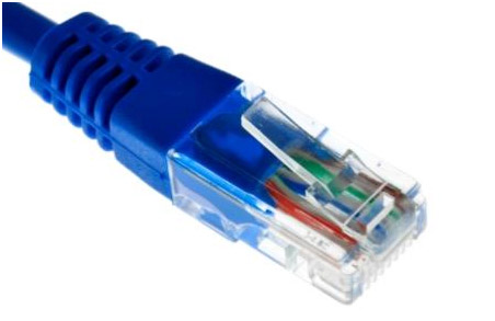
1. Inspect the RJ45 Connector
Straight and crossover cables are wired differently from each other. One easy way to tell what you have is to look at the order of the colored wires inside the clear plastic housing. The RJ45 connector is the standard type connector used for Ethernet connections. It is noticeably wider compared to the smaller RJ11 connections used on older telephone cords.
2. Compare Both Ends Side by Side
You need to hold the physical cable up to a light source. Put both ends of the cable side by side with the locking connector clip facing the exact same way. Look closely to see if the order of the colored wires is the same on both ends.
3. Determine the Wiring Result
If the colors match perfectly from left to right, then you have a straight cable. If the color patterns differ, then it is most likely a crossover cable. It could also just be wired completely wrong by the manufacturer.
Standard Ethernet Wiring Schemes Explained
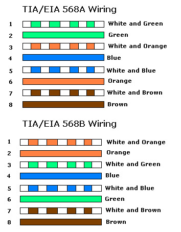
1. Choose Between 568A and 568B Standards
There are two commonly used standards for wiring Ethernet cables. They are known in the IT industry as T568A and T568B. It is entirely up to you which one you want to use for your personal network projects. The 568B standard is significantly more common in modern commercial installations.
2. Wire a Straight Through Cable
For straight cables you must make sure both ends are wired the exact same. You choose either the A or B standard and apply it to both RJ45 heads. Simply follow the color order shown on the chart below while attaching the ends onto the bare copper cable. You will need a specialized crimping tool to lock the metal pins into place permanently.
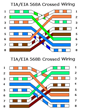
3. Wire a True Crossover Cable
Building a crossover cable requires a split configuration strategy. You must wire one end of the cable using the 568A standard. You then wire the exact opposite end using the 568B standard. This swaps the transmit and receive pins so two identical hardware devices can communicate directly. Make sure that each end is wired according to one of the exact diagrams below.
For additional training resources, check out our online IT training courses.
Check out our extensive IT book series.